Microwave System Design Tools And Ew Applications
This page contributed by Mario LaMarche of Mercury Systems. For more on electronic warfare,
Go to our page on electronic decoys,or check out the entire Navy Handbook on Radar and Electronic Warfare in pdf format for you to download.
Check out our page on the Association of Old Crows.
See our page on the history of electronic warfare (also contributed by Mario LaMarche!)
Why do microwave engineers have the most fun designing electronic warfare (EW) hardware? Unlike the design of a communications link or radar system, when designing an EW system, the other side of the link is unknown. For example, a microwave transceiver for a communications system operates over specified bandwidth, modulation scheme and power levels. When designing a radar receiver, the engineer knows what types of signals to expect. However, when designing an EW system to jam a radar or detect a radar, the details of the radar are not known. This is why EW systems require broadband, high-dynamic-range microwave hardware—which is arguably the most fun to design.
What is Electronic Warfare?
The most common objective of electronic warfare is to protect one's own use of the electromagnetic spectrum (EMS) while interfering with the adversary's use of the EMS. Since this is such a broad field, we divide it into three groups based on application: electronic support, electronic attack and electronic protection.
Electronic Support
Electronic support (ES) is the set of technologies and methods designed to receive and analyze an adversary's transmissions of electromagnetic signals. This includes locating the sources of radar signals as well as identifying the adversary's communication signals. Ever wonder how a fighter pilot knows when an enemy has a missile-lock on them? That's electronic support.

https://www.jbsa.mil/News/Photos/igphoto/2000502272/
One example ES system is the radar warning receiver (RWR). The purpose of these systems is to detect and analyze radar signals in order to provide actionable information. For example, a radar detector in a car will detect police radar to notify the driver that if they don't slow down they might get a speeding ticket. As described above, an airborne RWR will warn the pilot of an enemy's targeting radar.
Detecting different types of radars requires the RWR to operate over a wide bandwidth. Additionally, maximizing the range of the RWR requires a low noise figure. To see more detail on the challenges of developing RWR technology, take a look at my blog post on electronic support.
Electronic Attack
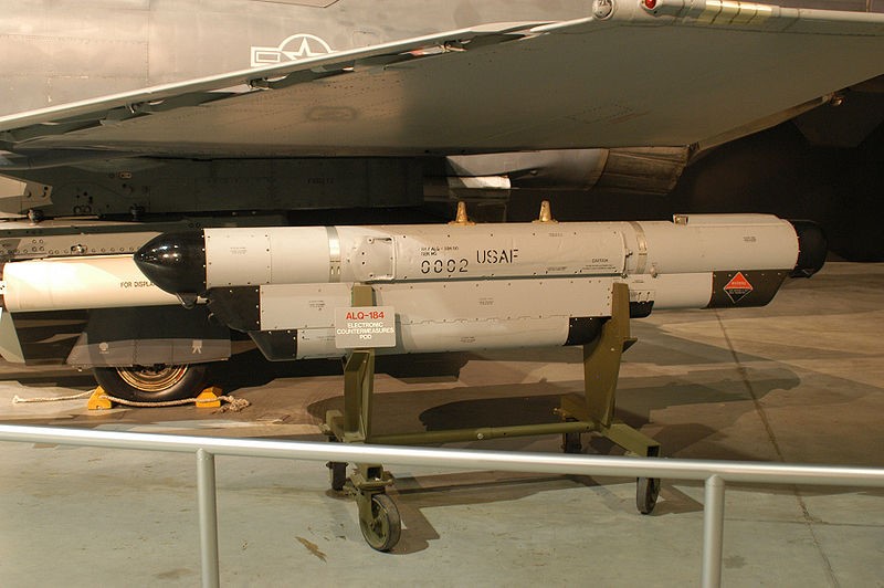
Electronic attack (EA) is a key component of electronic warfare and includes the set of technologies and methods that use electromagnetic energy or anti-radiation weapons to attack personnel, facilities or equipment. Most commonly, EA is used to impact an adversary's use of the EMS.

https://commons.wikimedia.org/wiki/File:AN-ALQ-184.JPG
Radar jammers are a type of electronic attack technology that either blinds a radar with high-power noise or generates false targets to obscure the true location of the target. A radar system identifies a target when the energy reflected from the target is greater than the radar receiver's noise floor. If the reflected signal is below the noise floor, it becomes much more difficult to recover. By transmitting high-power noise, a jammer can cause the noise floor of the radar receiver to increase, thereby decreasing the range and sensitivity.
A more complex approach is to modify the radar signal to create false targets. This usually involves a digital RF memory (DRFM) system that receives the radar signal, modifies it, and then retransmits the modified signal. Using low-latency hardware, the radar signal is either down-converted and digitized or directly digitized. Real-time processing modifies the signal by altering parameters such as the phase delay. The modified signal is then converted back to analog and transmitted to the radar receiver. The digital signal processing allows for a wide range of custom algorithms that create false targets or perform other operations to obscure the true location.
While easy to describe, implementing this technology is extremely difficult. The system must have very low latency such that it can digitize and process the radar signal in real time. Similar to the radar warning receivers, DRFM systems must be broadband with low noise figure in order to maximize flexibility and range.
For more information on radar jamming, see my blog post on electronic attack.
Electronic Protection
Electronic protection (EP) is the set of technologies and methods that protect against the effects of electronic attack (EA). When an EA system attempts to jam a radar, the radar's EP technology resists the jamming.
It's important to make the distinction between the self-protection element of electronic attack and electronic protection. A self-protection jammer provides protection from a radar-guided missile and is including under electronic attack since the jammer "attacks" the radar. In this case, electronic protection would be a feature of the missile's targeting radar designed to provide protection from the effects of the jamming.
While there are quite a few techniques to protect against electronic attack, the below describe some of the main concepts:
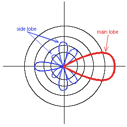
Sidelobe-Blanking: In this image, we see a plot of antenna gain as a function of direction. While the main lobe has the greatest gain, a signal originating from a direction corresponding to a sidelobe is also received. By reducing the sidelobe levels, the radar antenna is able to focus on the target and will have reduced sensitivity to a jamming signal originating outside of the target area.

Radar Detection: Before a jammer can affect a radar, it must first detect the radar. This is often the role of an electronic support system. By modifying the radar signal to make it more difficult for the adversary to find, it becomes more difficult to deceive the radar. For example, reducing the length of the radar pulses can make them more difficult to detect.
Radar Burn-Through: Radar burn-through describes the maximum distance from the jammer to the radar for which the jamming is effective. For the jamming to be successful, the power level of the jamming signal at the radar receiver must overwhelm the power level of the actual reflected radar pulses. From the perspective of the radar system designer, increasing the radar's transmit power improves the radar's ability to resist jamming. With a higher radar output power the received radar reflection is larger and therefor easier to detect in the presence of interfering signals.
Frequency Agility: In terms of radar, frequency agility is the ability to shift the operational frequency to mitigate the effects of jamming and other forms of interference. By operating over multiple frequencies, a radar system is more likely to find a frequency outside the range of the jammers. Additionally, by quickly shifting frequencies, a radar system can actively stay ahead of the countermeasures. Even if a jammer is able to operate over the radar system's frequency range, it takes a finite amount of time to determine and match the radar's frequency.
Waveform Diversity: In addition to adjusting the radar's operational frequency, the radar system designer can also adjust the specifics of the radar waveform. While the details of radar waveform shaping are outside the scope of this article, the concept is relatively straight forward. Optimizing the specifics of each radar pulse allows them to be easier for the radar receiver to detect and more difficult to jam.
For more details, take a look at my blog post on electronic protection.
Microwave System Design Tools And Ew Applications
Source: https://www.microwaves101.com/encyclopedias/electronic-warfare
Posted by: weeksmeren1965.blogspot.com

0 Response to "Microwave System Design Tools And Ew Applications"
Post a Comment